
Using the Layout-Space Feature efficiency in AutoCAD (2)
AutoCAD's layout feature is an essential tool for creating professional-looking drawings and presentations. Layouts allow you to organize your drawing sheets, set up different views of your design, add annotations, dimensions, and title blocks, and prepare them for printing or publishing.
🛈 Notice | Disclaimer:
This is the second part of the previously introduced topic on the difference between Model and Paper Space. To read now the first part, please click the following link AutoCAD Tutorials: Introducing Layout Features in 2D
 |
| Understanding Model and Paper Spaces; What you should know. |
Using the Union Command | Joining Solids
Now let’s see how the two solids objects you just created can be joined.
1- From the Edit panel, choose the Union button select the objects you want to be joined to, and press Enter. Alternatively, you can type UNI in the command prompt box. (See Fig.12 from the previous post)
2- Your drawing will look edges-free at the junctions, smoother, and more realistic, as the co-planar edges are now hidden and the form has been joined to appear as one entity. It also acts like one object when you select it. You now have a composite solid made up of two (or more) box primitives. (Fig.13 below)
 |
| Fig.13- Your drawing should look like this when using the Hidden mode from the Visual Styles list |
Now let’s add some geometric forms to our model and do the concept; Wanting it to have a more architectural look as a commercial building, we will be lightening the reception hall with a covering dome and providing it with a panoramic elevator serving the building on the side.
Also, three openings along the main façade, nicely decorated by a frontal triangular element on the top, will provide lighting to our office spaces through the glazy windows. It is likely good to provide some big openings connecting the reception level to the outside.
And so, starting from creating those elements, all you have to do is draw five equally distributed rectangles along with the 9-unit length of the base box. To do so we will use the appropriate tools, as follows:
1- First, draw a line of 9 units in length parallel or overriding the similar lower edge of the model. Type "Divide" or "DIV" in the command prompt box. Then at the Select object to divide: prompt, select the last line drawn, and press Enter.
2- Enter the number of segments or [Block]: prompt, type number 6. Five-point nodes equally distanced appear along the selected line.
3- You can adjust the type and the size of the point as you desire in the DDPTYPE tool.
4- You have just specified the exact location of the five openings you will add to the model in a while. Now draw a rectangle of (0.2x1) anywhere you want in the current drawing. You can do it by entering REC in the command prompt, and at the Specify first corner point or [Chamfer/Elevation/Fillet/Thickness/Width]: prompt, we will click any point on the modeling space to specify the corner of our rectangle and then at the Specify other corner point or [Area/Dimensions/Rotation]: prompt, we will have to enter the value of (@0.2,1) to end the command.
5- Start the EXTRUDE command and select the last created rectangle to extrude it by 1.5 units. We now have a solid box ready to be used in our model.
6- Now, initiate the MOVE command and pick the solid you have just drawn from the middle of its lower edge as demanded in the Specify base point or [Displacement] <Displacement>: prompt, and press Enter. Use the Midpoint Osnap override when picking the middle of the edge of the solid for accurate transportation of the solid.
7- At the Specify second point or <use first point as displacement>: prompt, pick the node on the line already defined in step 2 above while handling the selected solid from its mid-lower edge.
8- COPY the moved solid starting from the same base point picked before and make another four copies at the remaining marked nodes.
9- Your drawing should look similar to Figure 14 below.
 |
| Fig.14- The openings in the Ground Level copied to their actual places |
A similar procedure of creating those openings is to be repeated on the other side of the building and you should handle it with ease and quickly. If not have a brief look back over the previous chapters to refresh your mind!
Using the Editing Tools for the 3D Solids
You now have the eight openings primitives, but you still need to define their relationship to the initial composite model you created earlier from the two primitive boxes.
1- Choose Subtract from the Edit Panel, or type SU in the command prompt.
2- Select solids, surfaces, and regions to subtract from .. Select objects: prompt, select the biggest solid, and press Enter.
3- Select solids, surfaces, and regions to subtract .. Select objects: prompt, pick all the eight smaller solids created so far as per the dimensions (0.2W x 1L x 1.5H) units, and press Enter after you finish.
4- The small individual solids have now been subtracted from the whole model. To have a more realistic view of the model just switch to Hidden-Line mode in the Visual Manager window and you will visualize your model more clearly.
Creating Complex Primitives
As you learned earlier, you can convert a polyline into a solid model using the Extrude from the Edit Panel. This process lets you create more complex primitives thanks to the options provided within the command.
In addition to the simple straight extrusion you’ve already tried, you can also extrude shapes through curved paths, or you can taper an extrusion as well.
Next, you’ll have to draw an isosceles triangle aligned to the XY working plan (*) of a newly defined UCS, parallel to the Front view, and has an origin in the upper left corner of the model, as shown in Fig.15 below. Also, you will have to generate a path along the upper edge of the composite solid using the 3DPolyline tool (or typing 3DPOLY) from the Draw panel.
 |
| Fig.15- Path-Extrusion of a closed 2d Polyline using a 3D Polyline. |
Having those two objects created, you still have to apply the extrusion process to them.
1- From the Edit panel choose again the EXTRUDE tool or type EXT in the command prompt. Select the triangle at the Select objects to extrude or [MOde]: prompt, and then type PATH or P from the following options to choose from: Specify height of extrusion or [Direction/Path/Taper angle/Expression] <0.0000>:
2- At the Select extrusion path or [Taper angle]: prompt, select the 3dpolyline object you just created. The resulting operation is wonderfully processed, as the triangle extrudes directed through its path, which acts as a real trajectory. For practice, you should give this option a try regarding the number of forms that every single path can create!
Now let's draw the triangular element on the top of the openings along the elevation. First, we will proceed with the openings; and for that, we will just change the XY working plan to overlap the frontal face where we want to create the openings. We will have to utilize the 3POINT method to do so for its easy-to-use and quicker results compared with others;
Note: We will discuss in further detail this topic and how to define and generate specific UCS with other methods, later in the 3D Modeling section.
Now, from the Coordinates panel, select the 3 Points command, then at the Specify origin of UCS or [Face/NAmed/OBject/Previous/View/World/X/Y/Z/ZAxis] <World>: _3 prompts, choose point O as the origin for the new temporary UCS, and point on the X-axis direction and pick any point you want for defining the new X-axis as per Specify point on positive portion of X-axis <1.0000,0.0000,0.0000>: prompt.
Finally, pick any point included within the Y-axis as per the prompt message Specify the point on the positive-Y portion of the UCS XY plane <0.0000,1.0000,0.0000>: which will end the command.
For instance, you can pick any point that is within the positive-Y part of the wanted XY Plan. Check the explicative figure 16 below for more clarification.
 |
| Fig.16- The newly defined XY working plan to draw the elevation openings |
Now draw the openings, following the measurements shown in Figure 17 below.
 |
Fig.17- The suggested measurement to follow to draw the three openings. |
Don’t forget to extrude those by 0.2 to show the difference of levels to the external elevation face, the same as we did for the below openings on the ground floor. Review the paragraph entitled “Using the Editing Tools for the 3D Solids” above, for a more description of a similar process.
Next, we still have to finish with the triangles on top of each of them.
1- With the same current UCS, draw via polyline an isosceles triangle of 1.0 unit height on the top of the first opening and copy it to the other two.
2- As for the triangle, and the object is a polyline, then we can extrude it into a solid.
3- Let's initiate the "Extrude" tool and at the Specify height of extrusion or [Direction/Path/Taper angle/Expression] <0.0000>: prompt, type 1.50, and press Enter.
4- While keeping the workspace set to 3D Basics, use the Slice tool on the Edit panel, to remove the excess of the prism previously created —i.e. the hidden part underneath the inclined top of the roof means the object created in the paragraph “Creating Complex Primitives”— To do so, type SLICE in the command prompt box.
Then, at the Select objects to slice: prompt, select the indicated object. Now, at the Specify start point of slicing plane or [planar Object/Surface/Zaxis/View/XY/YZ/ZX/3points] <3points>: prompt, press Enter to choose the default value suggested specifying the slicing plane to which the tool will act over the selected object.
You will then be prompted to specify the first, second, and third point on the plane where you want this slicing process to be done; Pick respectively the indicated 1, 2, and 3 points as shown in Fig.18 below.
 |
| Fig.18- The 3 requested points that form the slicing plane needed in the Slice tool. |
Then at the Specify a point on desired side or [keep Both sides] <Both>: prompt, pick any point on the desired part of the prism, which will remove the other part. As mentioned before, add a dome on the top of the reception floor, by using the Sphere tool from the Create panel.
Be sure to have the center of the sphere at the same level as the top of the ground level. At the end of this exercise, you should get the model shown in Figure 3 from the previous chapter.
Drawing Standard Top, Front, and Right-Side Views
One of the most common types of architectural drawing is an orthogonal projection. On the other side, what we used to call the Isometric View is another type of presentation similar to the perspective but with a parallel view instead of using a point of view to create an eye-like view.
If you have created a 3D model of a building using solids as we did in this chapter, you can use the tools described in the next section to generate 2D elevation drawings from your 3D solid model.
This style of technical drawing shows the Top, Front, and Right-side views of an object, and at worst produces vertical and horizontal sections of the model. Sometimes a 3D image is also added for clarity. Fortunately, you can derive such a drawing within a few minutes, once you have created your 3D solid model.
The first step is to select a sheet with a title block or to draw one. The title block commonly known as the drawing label consists of a border and an area in the lower-right corner or else reserved for notes and other drawing information.
🛈 A good application of the Attributes’ Blocks is to use them in creating Title_Blocks.
Setting Up a File with a Title Block
Usually, you can create a sheet layout with a title block from two methods:
A- Choose a template that comes initially installed in the AutoCAD Library and is stored in the "Template" folder. You can select the proper file regarding your preference such as architectural, mechanical, or else.
Let us choose the file named Tutorial-mArch.dwt for its architectural presets which might be helpful to our presentations, in addition to its metrical measurements adaptation. However, you still need to import your model drawing onto your template layout to continue working.
- Type (CTRL+N) to start a new file.
- From the Select Template dialog box, select the file named Tutorial-mArch.dwt or else, for the reasons discussed earlier, and then click Open.
- Use Save As… to save this file in another filename as you desire. Let us choose the name of 3D_model_layout.
B- The second method consists of creating your template by simply switching your initial 3d model drawing from the Model space to the Layout, also called Paper space mode represented as tabs in the lower part of your working area.
You can add more than one layout by right-clicking over the name of the tabs and from the menu selecting New Layout. What’s next is either applied in the two methods but we will be adopting method B.
What is Layout in AutoCAD?
While in the layout mode, utilize the VPORTS command to create the layout that works best for you. Select from a list of presets viewports. (Fig.19) It is a good idea to give a try any of them before starting your work to ensure which one is the right one for you.
 |
| Fig.19- The List of the Standard Viewports loaded in the VPORTS command. |
For architectural layout, you are mainly going to present your project as four viewports such as the top-plan view, in addition to the elevations and the sections. You can as well, add another viewport for the 3D view.
So in total, we will need a minimum of three viewports to have an appropriate layout to help our clients visualize the project in the clearest way possible.
How to use the layout feature effectively in AutoCAD?
Here's a breakdown of how to use the layout feature effectively in AutoCAD:
1- Creating a New Layout
- To begin, switch to the layout tab by clicking on the layout tab at the bottom of the drawing area or by using the "Layout" button on the status bar.
- You can create a new layout by right-clicking on an existing layout tab and selecting "New Layout" or by using the "Layout" dropdown menu and selecting "New."
2- Setting up Page Size and Units
- Once in the layout view, you can specify the paper size and units for your drawing sheet. This can be done by accessing the Page Setup Manager, where you can define the page size, orientation (landscape or portrait), and plot style.
3- Adding Viewports
- Viewports are rectangular areas on a layout where you can display different views of your model or drawing. You can add viewports by using the "Viewport" tool in the layout tab.
- After adding a viewport, you can adjust its size, scale, and position to display the desired portion of your model.
4- Arranging and Organizing Viewports
- You can arrange multiple viewports on a layout to display different views or details of your drawing. AutoCAD provides tools for aligning, resizing, and distributing viewports evenly on the layout.
5- Annotating and Adding Dimensions
- In the layout view, you can add annotations, dimensions, text, and other detailing elements to your drawing using the annotation tools provided by AutoCAD.
- Annotations and dimensions added in the layout view are independent of the model space and can be customized for presentation purposes.
6- Adding Title Blocks and Borders
- Title blocks contain information such as the project title, drawing number, author, and date. AutoCAD provides tools for adding and customizing title blocks to your layout.
- You can also add borders and frames to enhance the presentation of your drawing sheets.
7- Printing and Plotting
- Once you have finalized your layout, you can print or plot the drawing sheet using the plot command. This allows you to generate physical copies of your drawings or create digital files in various formats such as PDF or DWG.
8- Managing Multiple Layouts
- AutoCAD allows you to work with multiple layouts within a single drawing file. You can switch between layouts using the layout tabs and manage them using the Layout Manager.
By effectively utilizing the layout feature in AutoCAD, you can create professional-quality drawings and presentations that effectively communicate your design intent and specifications.
Creating New LAYOUTS and VIEWPORTS
Now you are almost ready to create your orthogonal views, and we mean by this term, all the views except for the perspective view, such as the top, front, and back. Side views, isometrics, and sections are also categorized here.
But before continuing, remember to switch back the workspace to Drafting & Annotation again to make access to the commands easier. Also, it is helpful to note that AutoCAD’s scales are set to work with drawings created only with mm or inches as units. So, if you’ve drawn your model in meters, then the simplest thing is to return to the Model space and Scale everything you’ve drawn by a factor of 1000.
1- First, you have to set the proper paper size to lay out your drawing. To do so, right-click over the Layout tab in the lower part of your UI. A menu will display, where you can select Page Setup Manager… > New… to define a new page setup. Name it Setup1 and make it current.
2- From there, set your new page layout to ISO expand A3 (420.00 x 297.00 MM) as paper size. As for the plot scale, type 1 mm = 1 unit in the related box; you will use these settings later to adjust your Plot Manager setup. (see fig.20)
 |
| Fig.20- Page Setup Manager dialog box. |
Start the VPORTS command and select the Three: Left viewport. Our model will then be shown in three different viewports. At the Specify first corner or [Fit] <Fit>: prompt, press Enter, and the three viewports will fit exactly into the blank white sheet, previously displayed, as shown in Fig.21.
 |
| Fig.21- The Layout displays initially the same model views in all three viewports. |
4- Now, double-click any of the viewports and choose the orthogonal view you want to be displayed. Let’s say the top view. You can do this from the Views panel > Top View in the drop-down list of preset views.
5- Make sure you unlock the viewport to allow you to use the zoom and pan commands, otherwise, the usage of those will be locked. You can do so by clicking the border of the viewport and choosing No from the Display locked quick property menu. It is also easy to change other viewport properties, such as its Standard scale, its Shade plot, or its Visual style from this menu. Choose 1:50 for the scale and 2D Wireframe for the visual style respectively.
6- Likely, do the same procedure for the remaining viewports by choosing other preset views, other visual styles, and even scales to display.
7- For instance, use the Section tool to make a section across your model. At the Select objects: prompt, select all the objects in your drawing. Then, on Specify first point on Section plane by [Object/Zaxis/View/XY/YZ/ZX/3points] <3points>: prompt, press Enter. You will be prompted to specify the three points that are on the plane where you want the section to occur.
You will have AutoCAD automatically create for you the polylines that intersect the model and the plane you choose for your section. A good idea is to create a specific layer, especially for the section process to use, and set its color to a remarkable color for an easy catch-eye. You can also fill it with a hatch pattern if you want.
To create a new viewport, create a new layout, or add it to your currently opened one. Getting on the Layout Tab, click on Rectangular in the Layout Viewports panel. Draw a rectangular viewport as you would a rectangle.
Your model space drawing (or a part of it) now appears in this new viewport. This viewport can be adjusted in terms of size, position, scale, etc... As before, clicking on the down-arrow beneath rectangular gives two more options:
- Polygonal allows you to draw a viewport with any shape you want. Think of it as drawing a polyline and using C to close it at the end of the drafting.
- The Object allows you to turn any sealed object into a viewport; draw a circle and try it.
There are other options– when you click on "Rectangle" look at the command line. 2, 3, and 4 options create sets of viewports arranged either vertically or horizontally within the rectangle you already draw.
The idea is to create a range of viewports showing various aspects of your drawing at appropriate and different scales. You can also copy and paste viewports. They will inherit the original scale but this can be changed later.
Finally, we will have 4 viewports a top view, a front view, a section, and an SW isometric view respectively as shown in Fig.22 below.
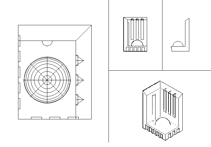 |
| Fig.22- You should have this same final Layout. |
And so, we did reach the end of the chapter, hoping that you by now learn how to benefit from using the Layout tool in your presentations. Just a reminder: This chapter introduced you to the power of "Solid modeling" tools in AutoCAD. Therefore, some of the 3D commands that appeared in this chapter will be revised again but with further details in the next chapters. Till then, stay safe, and catch you later!